In order to get a better undertsanding on how to use Olive Tree Lab, we recommend reading the Help Files. Below are some questions we have been asked and which we have shared with you. If you have a question which is not answered, please do send us an email and we will be glad to assist.
Installation and Activation
Installing Olive Tree Lab (OTL)
- For the trial version (valid for 21 days), download Olive Tree Lab and run the setup file. In order to access OTL trial, you will need an internet connection. You will then need to contact us to request a trial key to activate your trial.
- For Purchased licenses, once payment is made, you will automatically receive you activation key to activate your license.
Can I transfer my license from PC to PC?
- Your license can be transferred to another PC by clearing your license from one PC and activating the same license on another. To clear your license, please go to Help>clear license.
- For the Dongle (hard key) license, OTL can be installed on multiple PCs, and your license will be activated once you insert your dongle at any one given time. Please note that Dongles do not work with the latest 64-bit version.
What happens if I lose my license key?
- For electronic activation, contact us to re-send you license key or to deactivate it in the case your PC is lost or stolen and issue you with a new one.
- In the event that a Dongle is lost or stolen, this is equivalent to losing your licence for the software and consequently the cost to replace the licence(s) is the current purchase price of the software. In the event of a lost or stolen Dongle, Customer shall contact PEMARD without undue delay to notify PEMARD that the Dongle in no longer in its possession. PEMARD recommends that all Customers amend the software products purchased as an insurable item on their business insurance policies. Customers who have insured their software products against loss and/or theft may file a claim with their insurance company(s) in case the Dongle is stolen. Once a settlement value is received, Customer may contact PEMARD for further assistance.
My license key doesn’t activate.
Try launching OTL-Suite as an administrator (Right-click and select ‘Run as administrator’).
OTL-Suite text and windows are too small on my display
Some high resolution displays don't show OTL-Suite windows due to Windows updates. We have resolved this issue, however, if you are still faced with this problem, you can either set the font to 100% in the screen configuration, or if you are advanced in some coding yourself, you can try changing the manifest file as one of our clients did, and for which he has been kind enough to share with us. Download OTL manifest file.
There is a note at the top that says your graphics card does not support customizable legends. Is there a way to change settings to allow this?
Unfortunately there is nothing that can be done, this feature depends on the graphics card on your PC, a Graphics Card with Direct X 10 and above is recommended.
I can’t find installation files for previous versions of OTL-Suite
Setup files are available on our website for the latest version of OTL-Suite. If you need to re-install a previous version, please contact us and we'll send you the relevant setup files directly.
What happened to the 12-month PhD/Masters free license offer?
Unfortunately, it has come to our attention that on many occasions the license was used for commercial use, and we have had to withdraw this offer.
OTL-Suite is unable to create a New Project or open any of the Example Projects from the ‘Start Page’.
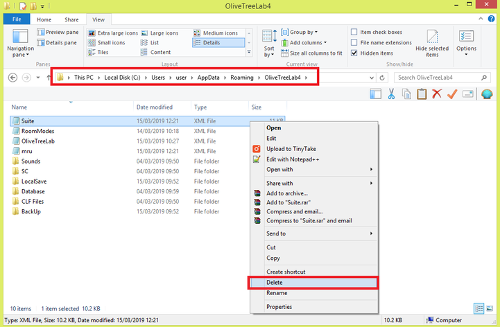
If you are facing an issue where you cannot create a new project or any of the example projects (including Isei’s Confgiruation) from the ‘Start Page’, close OTL-Suite and delete the file named ‘Suite.xml’ in the ‘OliveTreeLab4’ folder of your computer’s ‘Roaming’ folder. As an example, this can typically be found in the directory C:\Users\user\AppData\Roaming\OliveTreeLab4\. Then reopen OTL-Suite.
Alternatively, you could also be missing some missing some C++ redistributable files, please try to download this file on your computer :
https://www.microsoft.com/en-US/Download/confirmation.aspx?id=14632
https://www.microsoft.com/en-US/Download/confirmation.aspx?id=14632
If the problem persists please contact us through our support form or directly at [email protected].
Display
4K display problems - My text appears squashed and small when using OTL on 4k and high resolution displays.
If you are running your Windows computer on a high resolution display, you may have noticed that some text does not scale well, and are too small and squashed to read.
These issues may occur on any device that is connected to displays with a resolution greater than Full HD (1080p) and is caused by programs that are not optimized for high-DPI resolutions.
To resolve this issue, right click on OTL to open the Properties, go to Compatibility Tab, and select the "Change high DPI settings" option:
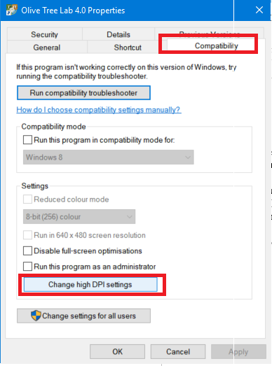
Tick the checkbox for "Override high DPI scaling behaviour" to select it.
Under "Scaling Performed by:", select the "System (Enhanced)" option:
Under "Scaling Performed by:", select the "System (Enhanced)" option:

Click Apply, and OK, then close.
Launch OTL and this should fix the issue.
Launch OTL and this should fix the issue.
Updates
Automatic Updates
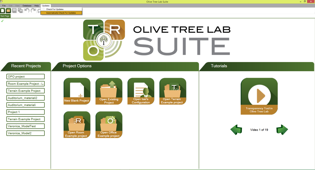
When an update is released, OTL-Suite will automatically update when the "Automatically Check for Updates" option from the ‘Updates’ menu in OTL is enabled.
updating issues for otl version 3.0X
- Some users using OTL version 3.0 may face an issue with a recent update of version 4.0. OTL may try to update itself even though no update has been released for version 3.0. This can cause the software to crash and then unable to re-launch. We highly recommend that you please disable the ‘Automatically Check for Updates’ option from the ‘Updates’ menu in OTL.
- If your software tried to update and you are faced with issues running OTL, uninstall and reinstall OTL v3. If you do not have the setup file for the last version (3.5.1) available please contact us in order to send it to you.
Migrating and updating database to latest version
OTL-Suite v4.4 contains substantial new data entries in the database. In order to take advantage of these new materials and keep the entries from your old database (created in OTL-Suite v4.3 or earlier) please follow the procedure in the following document: Guide to backing-up and updating the local database of OTL-Suite v4.4
Modeling
How do I create a model in Olive Tree Lab-Suite?
- OTL-Suite provides some CAD tools to assist you in modeling. The tools are found in the ‘CAD Tools’ window. Alternatively you can also import a DXF/DWG file directly into OTL-Suite making sure your model is exploded first before importing.
How do I import a 3D CAD model?
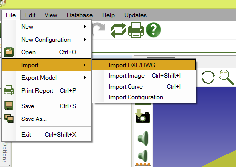
To import a 3D CAD model use one of these methods:
- File >Import> import DXF/DWG:
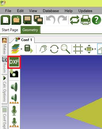
- Dxf button from the tool bar found on the left hand side of the geometry viewer.
- If the .dxf file also includes surfaces it is best select the ‘Optimised’ option in the ‘DXF Import Settings’ window. If the original file has too many surfaces it is best to import the lines only and create the surfaces in OTL-Suite. You will also need to ensure that you are selecting the correct units that correspond to the units of your original CAD model.
- Make sure that your all surfaces have been exploded in your original DXF/DWG file.
When importing a .dxf file is it better to import the faces or the lines? Why is it that when I import faces the surfaces are split?
- A: When you import a DXF/DWG model with surfaces, it’s best to choose Optimised, this will reduce the number of triangulations in OTL-Suite. For surfaces which are still too many, then it’s best to create the Walls in OTL-Suite directly. Also please make sure that if the model you are importing is in mm for example, to select mm when importing in order to maintain the scale:
Is there a limit to the number of surfaces OTL-Suite can handle?
- OTL-Suite deliberately has a limit to the number of entities imported, being 30,000 in order to minimise calculation time.
- There are some cases where models have over 30,000 entities, and fail to import. In order to reduce the number of surfaces, the first step is to export the model (say from sketch up) without lines, I.e. Only faces.
- Due to the precise nature of the calculations, in practice any model in OTL-Suite should be much smaller in order to calculate efficiently. An effort should be made to constrain the size to a maximum of 300-500 surfaces. Here is a list of methods that can be done to limit the size of a model:
- Make any surfaces that are not acoustically significant inactive. The surface that is inactive will still be present in the viewport for illustrative purposes but will not be taken into account in the calculations.
- Make sure that non-rectangular surfaces are optimized. If the two coplanar surfaces were created separately it is best to redo them again as one surface using the ‘create surface on existing points’ tool from the ‘CAD Tools’ window
I imported a model based on GIS coordinates and I get an error when running calculations. What could be causing the error?
- IF importing a model from GIS coordinates the coordinate values could be extremely high. Therefore, the model should be sent close to the origin by right clicking any selected object and clicking the ‘send to origin’ option. This will shift the entire model to the origin.
How do I ensure that my room normals are pointing the correct way?
- In order to see the normals of a surface, select the "show/hide normals" tool from the "cad tools" window or press n on your keyboard for shortcut, where the reflected sides will be displayed as opaque and the non-reflective sides will be displayed as transparent. Double sided surfaces are shown as opaque.
- The normals are also indicated as cones. For room acoustics and open-plan office calculations, use the "auto correct normals" from the "cad tools" window and ensure that the normals are pointing inside the room prior to calculations.
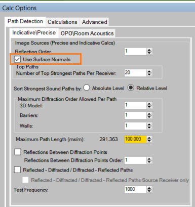
- For outdoor calculations, users can calculate without using the normals. Should you wish to calculate using the surface normals, ensure you select the use surface normals in the ‘Calc Options’ side panel
Can I import images in OTL-Suite?
- Yes, users can import google earth images or any other 2d image in order to assist in the modelling of the project.
- If importing from google earth, in order to ensure that the scale is the same, measure the distance between source and receiver using google earth’s ruler tool. Then measure the distance of the area horizontally and vertically and import the image using the same dimensions.
Is OTL-Suite capable of adding line sources?
- Yes, OTL can draw line sources. To draw a line source, click on line source icon, click on point where you would like your line source to start from, draw a line and click on the point where you would like your line source to end. You will be asked to enter a separation distance between sources or angle between 2 consecutive sources and a receiver (in case you have already placed a receiver) and specify the line-source heights (beginning and end). See section Inserting Noise Sources in Help Files.
- Line sources are grouped and are edited collectively. To split your line source into individual sources, select the line source, right click with your mouse and select the ‘Convert Line Source to Individual Sources’ option from the right-click menu. Please note that once converted, you can not change the individual sources into a line source, you would need to redraw it.
Is OTL-Suite capable of adding line receivers?
Yes, inserting a line of receivers works the same way as line source, with the exception that receivers are not grouped as one entity. To select multiple receivers, you still need to select them all either from the object tree or from the viewport using Ctrl/Shift and click with your mouse. You can then change their properties collectively. See section Insert Receivers in Help Files.
Is it possible to insert a planar noise source?
- It is not possible to insert a planar noise source in OTL-Suite, however if you place multiple line sources at a fixed distance from each other and set the 'source contribution' option to 'coherent' in the ‘Calc Options’>’Calculations’ side panel then the sources will act as a planar noise source. The source spectrum of the individual line sources will also need to be reduced so that when combined they are equivalent to the level of the planar noise source.
What’s the difference between walls and barriers?
- Barriers have different calculation results, in that they take into effect calculations before and after the insertion of a barrier. Whereas if you wanted to see result before and after a remedial wall, you would need to specify that wall as remedial in the walls property panel found in the right hand side of the geometry viewer.
- Walls are disregarded in indicative (estimated) calculations to give faster results. Indicative calculations take into account sources, receivers, grounds and barriers and disregard all other entities.
- Barriers can also take certain predefined shapes, whose parameters can be controlled in the ‘Barrier’>’Shape’ side panel, making it easier to perform parametric studies.
What are patches and how do they work?
- Patches are used in OTL-Suite to investigate the effect of a remedial surface that will be added on the walls of a room (such as sound absorbing panels). The way they work is that when creating a patch on a wall, a hole is created in the wall and the hole is replaced by two surfaces:
- The patch, which can have different acoustical properties and is remedial (therefore is only taken into account in the ‘After’ calculations)
- The wall behind the patch, which has the same acoustical properties as the original wall, but is only taken into account in the ‘Before’ calculations.
Therefore you can easily see the effect of the absorption panel by comparing the EA before (which is the calculation corresponding to the wall behind the patch) with the EA after (which corresponds to the patch being included).
Should I model absorption panels with a wall or a patch?
- Either can be used as OTL-Suite considers patches to be walls. Determining which ones should be used will depend on the way the absorption panels are to be installed in the space under study”
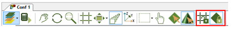
- If the absorption panels are to be installed on a wall of the room, then it is recommended that patches are used to model them. This is because when a patch is created on a wall an additional surface behind the patch is created (with the same acoustical properties as the original wall) which will not be included in the calculations that involve remedial surfaces. Start by modelling your room using walls and then draw your absorption panels on the wall using the “Create Patch” tool from the “CAD Tools” window.
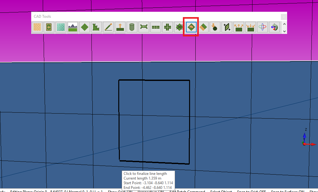
Make sure you have the “Snap to Surface” option enabled or the “Snap to Grid” option from the top toolbar:
- If the absorption panel is free standing, then it is best to use a wall to model. You will need to make the wall a remedial surface by selecting the wall and setting it to be remedial from the wall side panel. When setting the free standing absorption panel to remedial OTL-SUITE will again run two calculations one excluding the remedial surface and one including it. You will also need to make the wall double sided so that both sides of the wall are taken into account in the calculations.
I moved a patch to the wall surface rather that creating the patch directly on the wall using the ‘Create Patch’ tool and it doesn’t show any attenuation even though the patch material is more absorptive.
- The way patches work is that when you draw a patch on a surface a hole is created on that surface which is replaced with the patch (which is remedial) and the wall behind the patch.
- Thus if you make the patch and the wall behind the patch transparent you will see a hole in the original surface.
- When the remedial patch is accounted for in the after calculations OTL-Suite knows to ignore the wall behind the patch thus avoiding any possible errors due to ambiguity of two surfaces being on the same plane.
- Therefore try drawing the patches on the original wall surfaces again to ensure that a hole is created on the wall just to make sure that this wasn't causing any problems. Otherwise, in the remedial calculation the previous reflective wall is also taken into account.
How do I ensure that both sides of the free standing panel are taken into account for the calculations?
- If both sides of a surface are exposed to the room, select that surface, right click and select the “Make selected surface(s) double sided” option. This will create normal on both sides of the surface.
I have absorption data that has absorption coefficients greater than 1 due to the back side of the panel being exposed to the room as well
- Even when the absorption data for materials is above 1 in OTL-Suite you should always set your absorption coefficients to be less than 1.
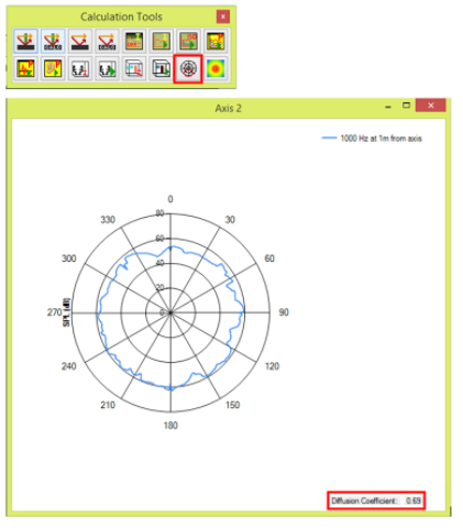
Is it possible to model diffusers when I begin working on higher frequencies that need the scattering coefficients included?
- OTL-Suite does not currently calculate the scattering coefficient but it does calculate the diffusion coefficient using the “Polar Plotter” calculation tool from the “Calculation Tools” window. Model your diffuser using the CAD Tools and then follow the instructions on how to use the Polar Plotter from the “Polar Plots". See Polar Plot section of the Help files.
If I model a panel that is exposed on both sides and would like to see the absorption of both sides, is there a minimum distance that I need to space the panel off the wall to ensure that rays make it to the other side on its way to the receiver(s)? Or is there a way I can tell if rays have reached to the back of the panel?
- Regarding a minimum distance of the side panels off the walls that will depend on many factors including the positions of the source and receiver. Most importantly however you would also need a high number of reflection orders (or maximum images to trace for room acoustics calculations) which will significantly slow down the calculation (the smaller the gap between the absorption panel and the wall the higher the orders of reflection needed). If you include diffraction in your model and enable the ‘Reflections Between Diffraction Points’ option from the ‘Calc Options’ side panel it should be easier to get paths to go behind the absorption panel.
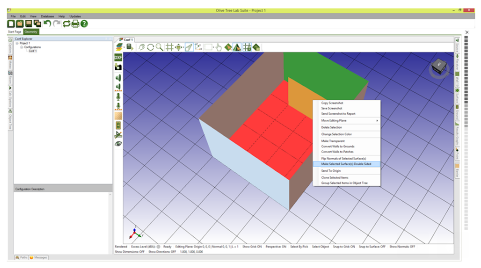
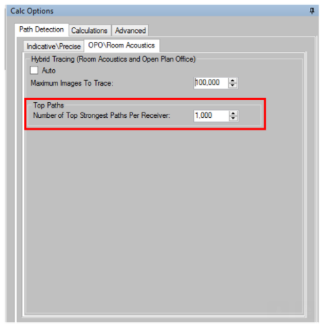
- You can tell if rays reached the back of an absorption panel using the ‘Show all Paths’ calculation tool but this only works for the precise calculation. However for Room Acoustics calculations (using the ‘Run Room Acoustics Calculation Tool’) the hybrid ray tracing method is partly stochastic so you can only see some of the paths after the full calculation is finished. Make sure you set the ‘Number of Top Strongest Paths Per Receiver’ in the ‘Calc Options’>’Path Detection’>OPO/’Room Acoustics’ side panel:
- Once the RA calculation is completed the top strongest paths will be shown in the viewport.
Is it possible to change a double sided wall/ surface back to single sided?
- You cannot change a surface from double sided to single. The surface will have to be remodeled
How do I select an entity?
- There are several ways to select an entity (source, receiver, ground, barrier etc). You can either click with your left mouse button on an entity once in the viewport to select it, double click on it to enable the corresponding panel to change its properties, or select it from the ‘Object Tree’ side panel.
I want to insert a noise barrier as a mitigation measure. Should I use a typical wall or a barrier?
- A barrier is recommended as this will give you the performance with and without the barrier, I.e. The effect of having a barrier, or not. Also changing the properties and shapes of barriers are easier. If you need a barrier which is irregular shaped, then create it as a wall, and select "is remedial" from the wall panel to get before and after.
- When running Indicative Calculations you must use a barrier as walls are not included in Indicative calculations.
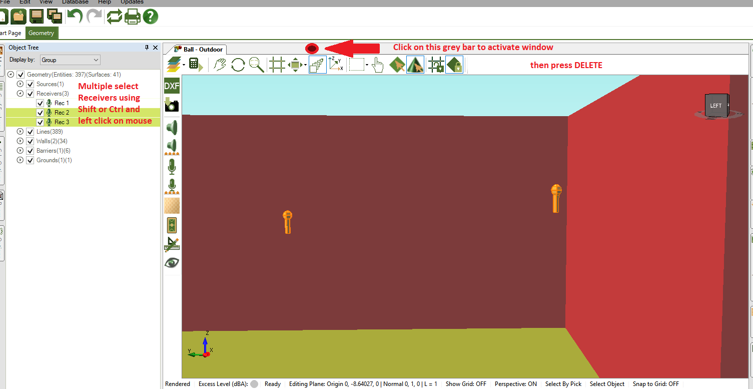
How can I delete an entity from the object tree?
- Select the object you wish to delete from the object tree, then click on the grey bar at the top of the geometry viewer to activate that window, and press delete:
How do I deactivate an object, such as a wall, barrier, ground, source or receiver?
- To deactivate an object, you need to make sure the inactive check box is unchecked in the relevant object’s side panel. Disabling it from the object tree only removes it’s visual representation from the model, but does not make it inactive:
When I measure the distance from a receiver to a surface, with snap to surface off and grid off options, how can I ensure that the initial point is the receiver and not on the other point in the atmosphere or elsewhere?
- It will snap at the point you click to start from, so if it sees the receiver, it will snap to the receiver. You will also see the red line which shows clearly where the measurement starts from. It's best not to have the snap to grid and surface on, as then it will look for a point either on the grid or surface.
How do I organise my model?
- OTL-Suite provides an ‘Object Tree’ side panel. The object tree outlines all the entities available in your configuration. Once you click on an entity in the object tree the corresponding entity will be highlighted in the geometry viewport for easy identification. You can choose to view entities by various categories:
- Group; grouped entities, i.e. If you have grouped some entities such as walls, or sources, or receivers, etc.
- entity; displays all the entities according to their selections, i.e. Sources, receivers, grounds, walls
- Type; displays the type of material assigned for grounds, walls and barriers and source spectrum and receiver criteria for sources and receivers
- State; displays whether the entity is active or inactive in the calculations
- Remedial; displays whether walls and barriers are remedial or non-remedial
- Colour; displays the entities according to the colours assigned to them
- Transparency; displays whether an entity is transparent or not.
- Group; grouped entities, i.e. If you have grouped some entities such as walls, or sources, or receivers, etc.
Is OTL-Suite able to model the directivity of sources for loudspeakers?
- OTL-Suite is able to import .cf2 files of loudspeakers and includes the directivity data in the calculations. To import a .clf file create a new source in the source database (either the local or project) and select the ‘CLF File’ option in the ‘New Source’ window. Then click the ‘Select Directivity File’ button to find the desired .clf file in the directory. Loudspeaker directivities are also available at www.clfgroup.org. Please note we do not offer support for third party software.
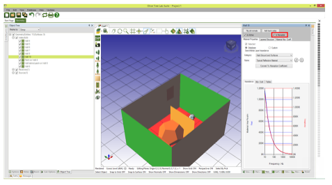
- An example of a source with directivity (.clf file) is shown below:
- Any other source that is not imported as a .clf file is assumed to be omnidirectional.
How can I create our own .clf directivity files?
- We suggest contacting the CLF group on how to author your own .clf files as we are not involved in authoring .clf files. Below is the relevant link of their website: http://www.clfgroup.org/author.htm
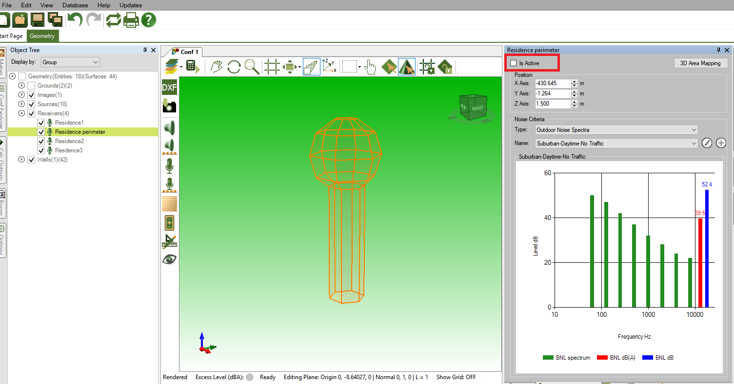
How do I include the background noise levels in my calculations? Can I import a measured background noise level?
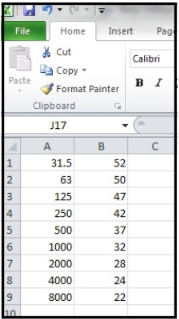
- The background noise level of your model can be set in the receiver criteria. You can either specify an NR rating available in the database, or you can import a custom spectrum by creating a new criteria in the database (either the local or project database) and clicking either ‘Import From File’ to import a .csv file with the background noise levels or ‘Import From Clipboard’ to import them from the clipboard.
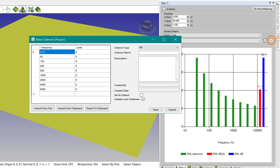
Note that the table being imported needs to consist of two columns, the first with the frequencies and the second with the background noise levels
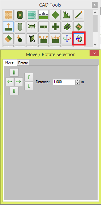
When I want to move an object, the grabbing point is always the center point of gravity. Is it possible to change this?
- Unfortunately, there is no way to change the grabbing point when moving an object using the 'Move Selected Objects' tool from the 'CAD Tools' window or the 'M' key shortcut. If you would like a more precise way of moving objects you can use the arrow key shortcuts which allow you to directly type in the distance you want to move the object along each axis:
- Select the object or objects you want to move.
- Press the either the 'Up'/'Down' key to move in the positive/negative y-axis direction, 'Right'/'Left' key to move in the positive/negative x-axis direction or the 'PgUp'/'PgDn' key to move in the positive/negative z-axis direction.
- Type in the distance (in m) you want to move your object in the selected axis and press 'Enter'.
- Alternatively, you could also use the controls in the 'Move' tab of the 'Move/Rotate Selection' tool in the 'CAD Tools' window.
How do I model trees in OTL-Suite?
- The best way to model trees is simply as vertical columns (where only the main trunk is modeled) created with the ‘Create Cylinder’ tool from the ‘Cad Tools’ window. The columns should be at least six sided.
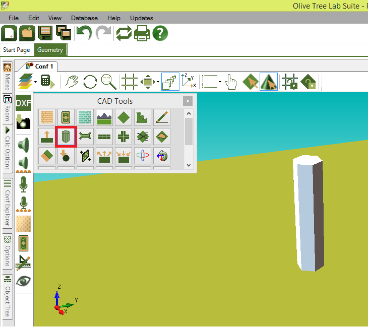
- If the hexagonal column created with the ‘Create Cylinder’ tool is too wide then follow this procedure to make them thinner:
- First delete all the surfaces except for the base of the column. You will need to separate the surfaces of the column to multiple objects before deleting them by selecting the column, right-clicking and selecting the ‘Separate Wall to Multiple Objects’ option from the right-click menu.
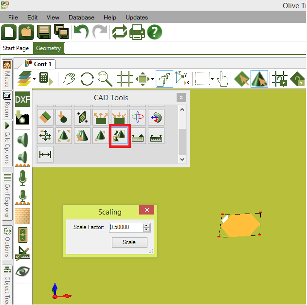
- Select the base (if it has been split into multiple surfaces after separating the column in Step 1, you will need to merge the different pieces again by selecting them all, right clicking in the viewport and selecting the ‘Merge Walls to One Objects’ optiom) and scale it down to the desired width using the ‘Scale Object’ tool from the ‘CAD Tools’ window. You can find more information on how the ‘Scale Object’ tool works in the ‘Using CAD Tools’ section of the help files.
3. Once the base of the column has been scaled down to the desired width, extrude it to the desired height using the ‘Extrude’ tool from the ‘CAD Tools’ window.
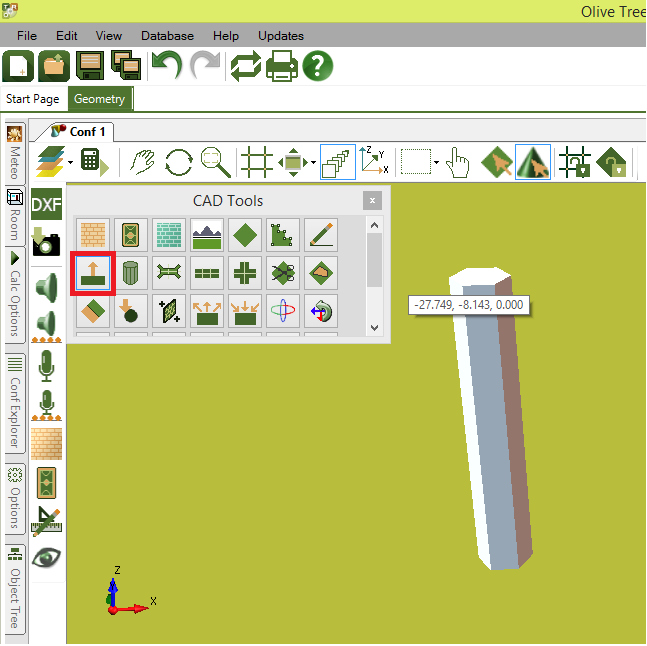
Alternatively, it might be easier to create the columns in a CAD program like SketchUp and import them as a DWG/DXF file.
I am using a line source in my model to represent traffic noise. What should the spacing between the individual sources be?
- When using a line source to represent traffic, the spacing between the individual sources should depend on the how busy the road is. The busier the road, the shorter the spacing between the individual sources should be and vice-versa.
- One good way to do this is to base the source separation on the representative distance between cars in the google maps satellite image of the location you are modelling. Please bear in mind that too many sources will also have an effect on calculation time.
What is the difference between walls and grounds?
- The difference between walls and ground is that grounds do not diffract sound paths from their edges whereas walls do. Also grounds cannot be made remedial, while walls are not included in indicative calculations.
OTL crashes when placing a receiver, or any 3D entity (e.g. desk layouts) and all 3D source symbols will only allow spheres
This is likely a .NET Framework issue, although the latest .NET Framework may be installed and should work with all applications requiring older versions of .NET Framework, you may need to edit the registry to allow it to work with ALL applications. To do so, please follow the below instructions:
Alternatively, you could also be missing some C++ redistributable files, please try to download this file on your computer
https://www.microsoft.com/en-US/Download/confirmation.aspx?id=14632
- Open Registry Editor by typing regedit in the Search Bar.
- When the Registry Editor opens on the left side navigate to HKEY_LOCAL_MACHINESOFTWAREMicrosoftNET Framework SetupNDPv4Client
- Find the key called Version. Find its value and remember it or write it down, because you may need it later.
- Now right click the Client entry on the left side and choose Permissions.
- Click the Advanced button.
- Find the Owner section on the top and next to the TrustedInstaller click Change link.
- In Enter the object names to select field enter Administrators. Click on Check Names button. If everything is in order, click on OK.
- Click Apply and OK to save your settings.
- Try to launch OTL and insert a Reciever or 3D entity.
- It should work at this stage, if not you may also need to also change the Value of the Version key in Registry Editor to 4.5.0. Click on OK to save changes.
- In Registry Editor navigate to this path once again: HKEY_LOCAL_MACHINESOFTWAREMicrosoftNET Framework SetupNDPv4Client
- Find the Version key and set its value from 4.5.0 to its value from Step 3.
Alternatively, you could also be missing some C++ redistributable files, please try to download this file on your computer
https://www.microsoft.com/en-US/Download/confirmation.aspx?id=14632
Database
What is the difference between the ‘Local’ and ‘Project’ database
Entries created in a local database are available to all projects in OTL-Suite, while entries created in a project database are only available in the project they were created in.
How do I backup my database?
If you need to back up your database, do not uninstall OTL-Suite before following these instructions! If you do so you might lose your old database.
In order to keep the entries from your old database (created in OTL-Suite v4.2.1 or earlier) please follow the procedure in the following DOCUMENT.
In order to keep the entries from your old database (created in OTL-Suite v4.2.1 or earlier) please follow the procedure in the following DOCUMENT.
Calculations
What is OTL-Suite’s general approach in calculating sound propagation?
- Olive tree lab-suite is based on PEMARD’s methodology for calculating sound propagation. PEMARD’s methodology of calculating sound propagation is focused on preserving the wave based nature of sound and uses simplifications only wherever there is no practical alternative. For this reason, we always aim to use the latest and most accurate calculation models for our calculations, based on peer reviewed scientific publications. Extended material regarding the accuracy on our calculations can be found in our published papers.
How does OTL-Suite calculate path detection?
- Image source algorithm
- Hybrid tracing algorithm
What is OTL-Suite’s diffraction detection algorithm?
- We use an in-house developed algorithm for the detection of sound diffractions between any edge combination using the Broyden–Fletcher–Goldfarb–Shanno (BFGS) optimization algorithm, based on the work of Min and Qiu, and Hadden and Pierce
http://scitation.aip.org/content/asa/journal/jasa/69/5/10.1121/1.385809
and Erik Salomons:
http://www.ingentaconnect.com/contentone/dav/aaua/1997/00000083/00000003/art00008
- Sound diffraction detection is based on a proprietary algorithm that detects the path with the shortest time of flight between a source and receiver.
What are reflected diffracted paths/reflections between diffractions points?
- OTL-Suite detects, additionally to sound reflections and sound diffractions, paths that include both diffractions and reflections. These sound paths are important contributions to the sound field, especially in cases where a small number of wave fronts arrive at the receiver, like in outdoor sound barrier cases.
How does OTL-Suite calculate sound paths?
- For the calculation of the sound paths and the final frequency response estimation, OTL-Suite uses a number of calculation methods to calculate the different effects on sound. You can read more in Section Theoretical Background in the Help Files.
How is sound attenuation taken into account in OTL-Suite?
- Currently all sound sources in OTL-Suite are considered to be point sources which emit spherical sound waves. Even OTL-Suite’s line sources are composed by a number of point sources. Theoretically, all other types of sound sources can be reproduced by using point sources. Therefore, sound pressure attenuation is based on the spherical wave attenuation.
How does OTL-Suite calculate sound reflections from surfaces?
- There are two ways to calculate the effect of a sound reflection on a sound wave in OTL-Suite. These are a) by calculating a material’s impedance and using it for the calculation of the material’s reflection coefficient and b) by using measured data like absorption coefficients. OTL-Suite supports both ways of calculation.
Sound reflections based on materials impedance
Calculating the reflection coefficient based on the material’s parameters is the most close to reality method for calculating the effect of sound reflections. The main reason for this is that the angle of incidence is taken into account. OTL-Suite includes calculations of material impedance for both semi-infinite materials as well as multi-layered structures. Impedance from multilayered structures is calculated using Vigran’s model. OTL-Suite also supports two models of sound impedance calculations 1) Delany-Bazley’s 1-parameter model (Acoustical properties of fibrous absorbent materials, Delany and Bazley, 1970) 2) Allard’s 6-parameter model.
Sound reflections based on absorption coefficients
Despite the fact that calculating the sound reflection coefficient from the impedance material is the most accurate way to calculate the effects of sound reflections, unfortunately material parameters are not widely available. On the other hand, measured absorption coefficients for different materials are much easier to find.
I want to define the absorption coefficient of a surface. I know the normal-incidence absorption coefficient, is this the correct input needed for OTL-Suite?
- Regarding using absorption coefficients in OTL-Suite, only statistical absorption coefficients can be assigned to a surface. Therefore if only the normal-incidence absorption coefficients are available they will need to be converted to statistical absorption coefficients as OTL-Suite does not have the means to calculate statistical absorption coefficients from normal-incidence absorption coefficients. However there are various methods for deriving the statistical absorption coefficients from a normal incidence absorption coefficient.
Does OTL-Suite use a diffuse reflection coefficient or angle dependend?
- Since OTL-Suite uses statistical absorption coefficients, then calculations will not take into account the angle of incidence of a path. If the calculations are outdoors then we recommend that impedances are assigned to the material, as impedances will take into account the angle of incidence of the paths and are the correct method for outdoor calculations. Perhaps you could look through the Material Properties database to find a material whose absorption coefficients are close to the absorption coefficients that you have available.
Can OTL-Suite calculate sound diffractions from edges
- Olive tree lab can calculate sound diffraction coefficients over multiple edges.
Does OTL-Suite support sound path summation?
- Olive tree lab supports two types of sound path summation, coherent summation and incoherent summation.
What are indicative calculations?
- Indicative calculations are faster calculations which run calculations in 1/3 Octave centre frequencies only, omitting any wall entities in the calculations, displaying results in 1/1 octave bands in the indicative graph (located in the results graph tab on the right hand side of the geometry viewport) after being appropriately processed.
What are precise calculations?
- Precise calculation results are displayed in high frequency resolution in the output window as well as in precise graph (shown in the results graph panel on the right of the geometry viewport). Also shown in 1/3rd and 1/1 octave bands after being appropriately processed from high frequency resolution results.
Which standards are applied in OTL-Suite?
- For Outdoor Sound Propagation, OTL-Suite includes ISO 9613-2. Users can run ISO calculations as well as PEMARD’s advanced calculation methods.
- For Room Acoustics, ISO 3382 Parts 1 & 2.
- For Open-Plan Office, ISO 3382 Part 3.
- OTL-Suite precise calculations run PEMARD’s algorithm based on a hybrid tracing approach and applies to both room acoustics and open-plan office calculations.
What is the recommended calculation setting for running room acoustics calculations?
- The user can choose between an automatic termination of the ray tracing process or a manual setting of the maximum images to be traced. If the automatic termination is chosen, the algorithm will try to detect when the correct result has been reached. If the automatic termination is disabled, the algorithm will terminate at the set maximum images to trace, with the principle being the more images traced, the closest the calculation should be to the actual result. Setting the Hybrid Ray Tracing Method to 50000-100000 images to trace should be enough for many cases although this is strongly dependent on the geometry of the room. It is best to start with a low value and gradually increase it until the results are converged.
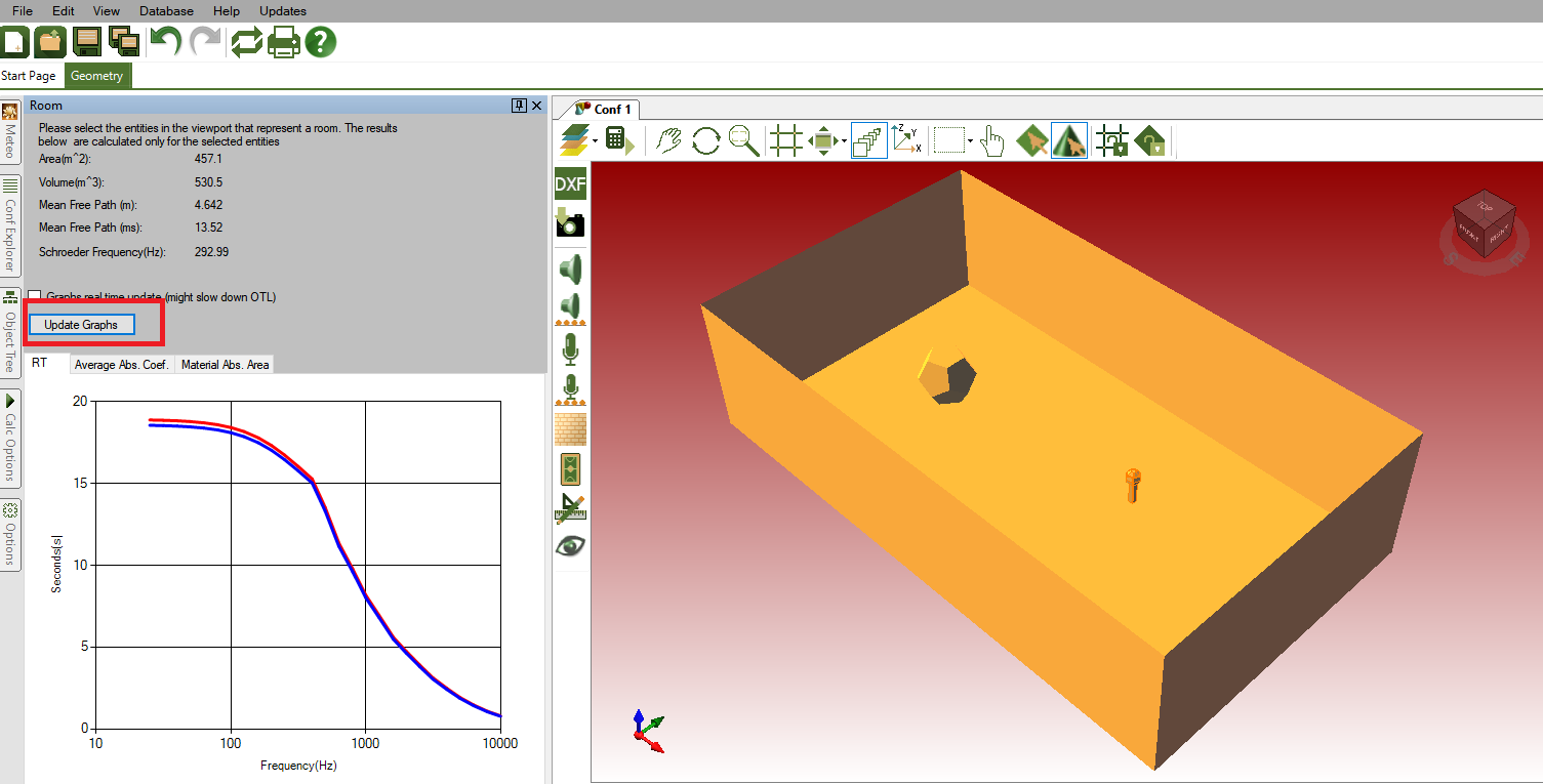
- If you want quick calculations which apply in the entire room volume (i.e. no need for mapping) use the Sabine/Eyring statistical models by pressing Ctrl+A in the geometry viewport and clicking the 'Update Graph' in the 'Room' side panel to see the RT levels (if you have any disabled or transparent walls in the Geometry, make sure you also select them from the Object Tree). In the same side panel you can also see graphs of the 'Average Abs. Coeff' of the room and the 'Material Abs. Area'.
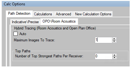
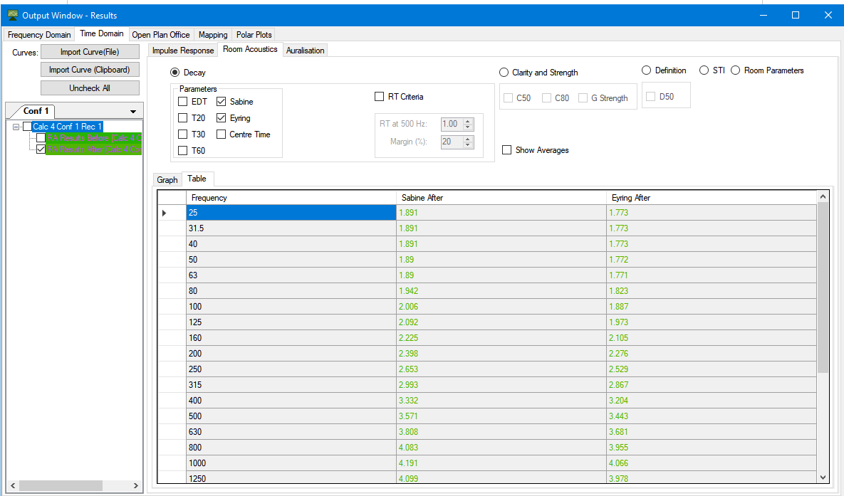
- The next quickest method to extract the results in a table form is too is to go to the Path Detection>OPO\Room Acoustics tab in the 'Calc Options' side panel, and then set the 'Maximum Images to Trace' field to 1 and 'Number of Top Strongest Paths Pr Receiver' to 0 (as shown in the screenshot below). Run Precise Room Acoustics calculation, and you can then get the Sabine/Eyring results in table form in the 'Output Window' which apply again in the entire room.
Can I calculate an impulse response?
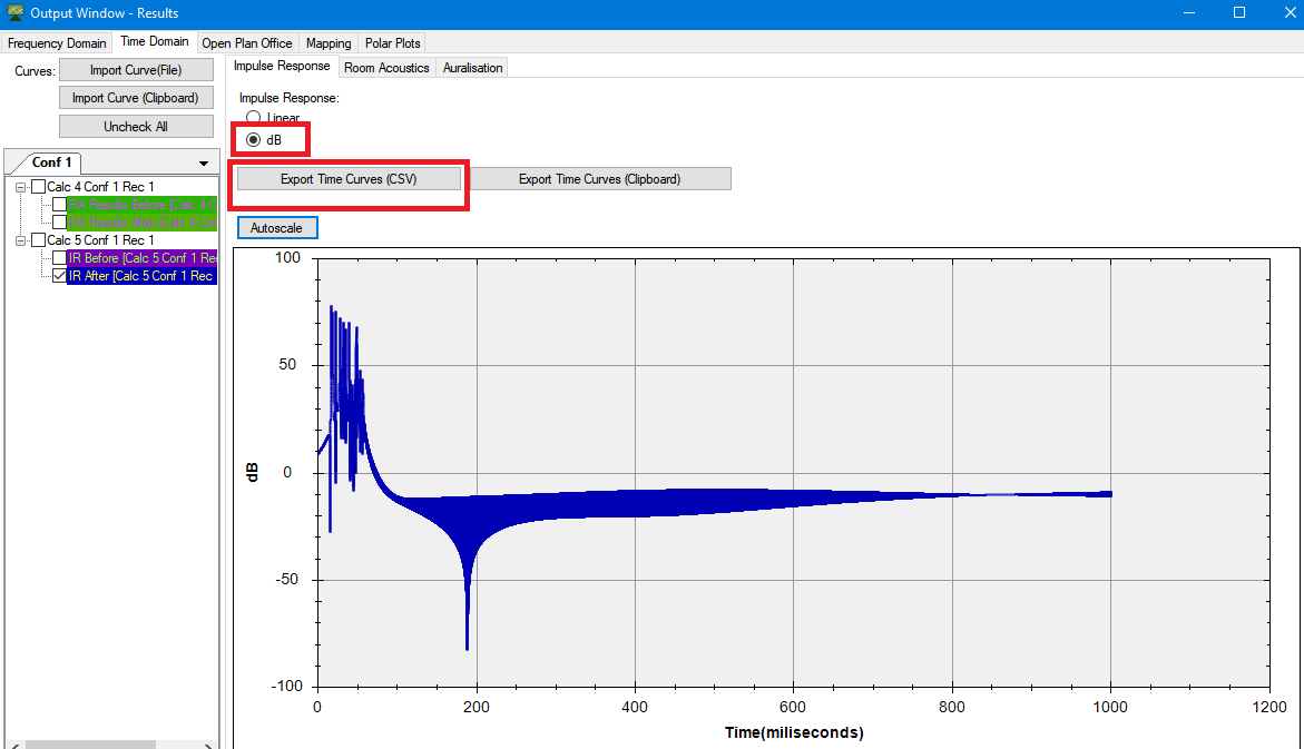
- Yes, in order to calculate impulse response, run impulse response calculations, found in the calculations menu. Results are shown in the output window, under the Time Domain tab.
- You must set the scale to default in order to properly view the curve. To do so, right click on the graph area, right click and select "set scale to default". Results can also be viewed in db.
Can I auralise in OTL-Suite?
- Yes, auralisation allows the user to take a calculated impulse response and use it to convolute either one of the built-in default sounds in OTL-Suite or an imported .wav file (provided the .wav file has a 44.1 khz sampling rate and a 16 bit depth).
- OTL-Suite also implements the Head Related Transfer Function (HRTF). This response will characterize how the human ear itself receives the sound from a point source. An impulse response for both left and right is calculated enabling binaural auralisation when the final stereo signal is heard through headphones.
What is the difference between the ‘Impulse Response Calculations’ and the ‘Auralisation’ calculation?
- The difference between the 'Impulse Response Calculation' and the 'Auralisation Calculation' is in the frequency resolution. The 'Impulse Response Calculation' is about half the resolution of the 'Auralisation Calculation' which has a CD quality resolution. The 'Impulse Response Calculation' is significantly faster however it needs to be interpolated up to a CD quality in order to be auralised. Therefore the 'Auralisation calculation' is more accurate but takes longer to calculate.
- Also, the HRTF is not calculated with the Impulse Response tool.
Can I create a .wav file of an Impulse Response without convolving it?
- In order to convert the Impulse Response to .wav file you will to export the Impulse data as a .csv file so that it can be used by a third-party solution to map the impulse response data points to the .wav file format.
Can I plot a 3d noise map?
- Yes, mapping allows the user to plot the level distribution over an area and view mapping in 2d or 3d. Mapping is calculated with a resolution of 1/12 octave band centre frequencies and shows calculation results in 1/3 octave bands between 25 and 10000hz over an area of receivers at a density specified by the user.
- For outdoors, results show IL, EA before and after, Lp Before and After, Lp After ISO broadband or in 1/3 octave band resolution. For Room Acoustics results show Reverberation Time and T30 and Open Plan Office results show STI.
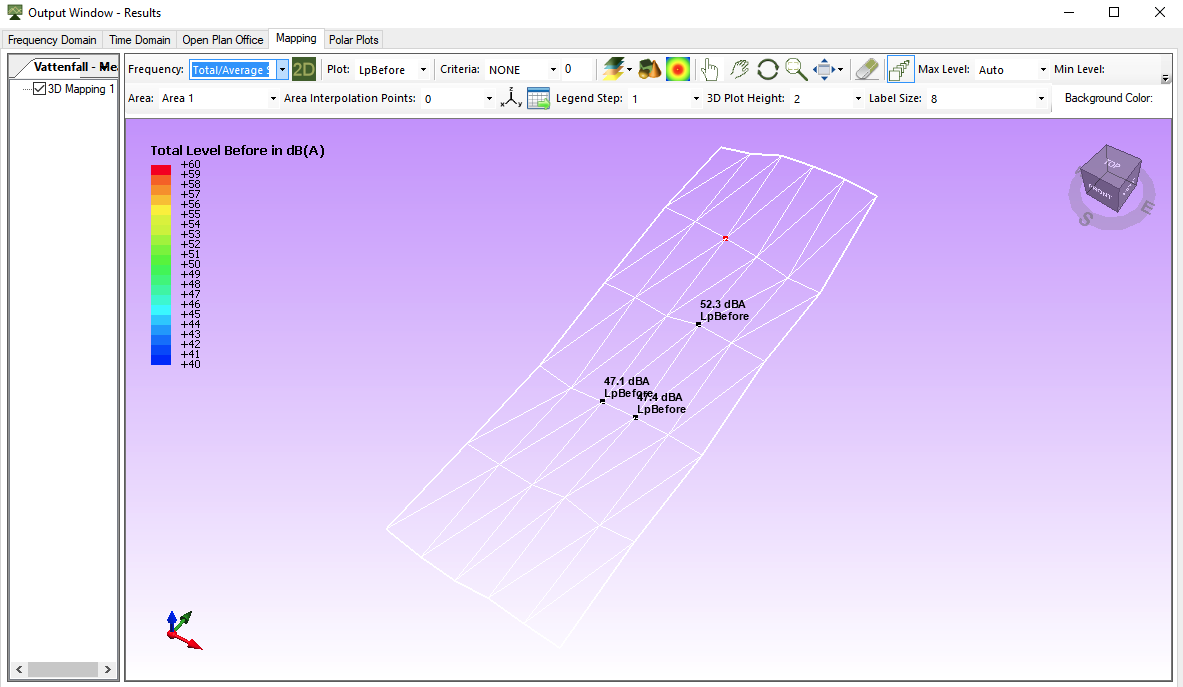
How can I tell what the exact dB values of the Sound Pressure Level are on a mapping plot?
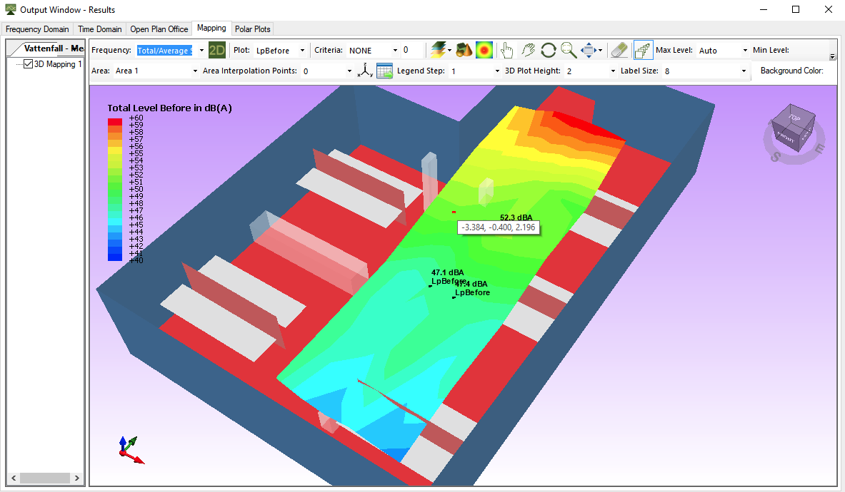
- To get the exact values of the mapping area, hover your mouse over a receiver point in the mapping area and double click. A label will appear with the exact dB value (or dB(A) if you have the 'Total/Average Spectrum' selected in the 'Frequency' drop-down menu in the 'Mapping' tab). When you hover over a receiver point in the mapping area, a red point will appear indicating that you can double click as shown in the screenshot below.
- You can edit label sizes to increase or decrease fonts, and you can remove the labels using the eraser icon at the top.
If you are having trouble finding the receiver points you can switch to wireframe mode from the 'Render Modes' drop-down menu (at the top centre of the 'Mapping' window toolbar). The receiver points are located at the vertices of the triangles.
You can also export all the values to the clipboard using the ‘Export to Clipboard button’ to further process in a third party program such as Excel.
Experiencing rendering issues in mapping?
- OTL-Suite requires a reasonably good graphics card, especially in relation to mapping in order to achieve excellent 3d rendering.
- OTL-Suite users who only have an on-board graphics card, may sometimes experience rendering issues while viewing mapping plots.
OTL-Suite’s calculations will not start or if they do they are very slow
- If the calculations in OTL-Suite are very slow or won’t start, the first thing to try to do is to reduce the number of surfaces in the model (see the ‘How big can a model be in OTL-Suite?’ question in the FAQ). Also reduce the number of reflection/diffraction orders in the ‘Calc Options’ side panel. Start with only 1 order of reflection to see whether the calculation is able to complete and then gradually increase the orders until the calculation time seems manageable. It is best to start with simple settings and then gradually increase the complexity iteratively.
- If there are still issues with the calculation time (or the calculations not starting) then contact us on [email protected]
Do lines play any role in calculations?
- Lines (as well as points) have no contribution to the calculations of OTL-Suite and are only included to aid in the construction of the 3d model, or for illustrative purposes.
If I want to calculate the sound level on a façade, how far should I place a receiver from a façade?
- It is best to place the receiver close to the façade, 0.1m should work well.
What is the ‘Maximum Path Length’ setting in the ‘Calc Options’ side panel?
- The ‘Maximum Path Length’ sets the maximum length of the paths that will be taken into account in the calculations. Any path with a length greater than the maximum path length will not be included in the calculations.
I made a mapping calculation but there are gaps in the calculated area I set up
- Most likely this is because no paths were found at the mapping points which are missing. To check add a receiver in one of those missing areas and run the ‘Show all paths’ tool, you can then adjust with the calculation options or geometry until you can find paths at that point. You may need to increase the order of diffractions/reflections in the calculation options and possibly reflections between diffraction points.
Does Sound Level Mapping calculation take into account directivity of the sources
Source directivity ought to be taken into account in the mapping calculations provided OTL-Suite has the directivity information. We recommend you try a mapping with one of the .clf files included in OTL-Suite.
I plan on calculating the modes of a room first (mapping) and locating pressure maxima to determine where bass traps would be most effective. Is OTL-Suite sensitive to the location of the panels and do you feel that it would help with this endeavor?
- Yes, that would be an effective way to do it. OTL will consider the locations of the panels so long as a sound path interacts with those panels.
Do incoherent sources alter the phase of the sources relative to each other and is there a way to adjust the amount of phase shift?
- All sources in OTL-Suite start with the same phase (at zero) and that phase cannot be changed. Incoherent sources have their absolute value summed up so any phase interference phenomena between different sources is not taken into account. If you set the sources to being coherent the phase interference phenomena is taken into account (you can set whether the sources are coherent/incoherent in the ‘Calculations’ tab of the ‘Calc Options’ side panel). You can find more information in the 'Theoretical Background' section of the help files.
What are the differences between the ‘3D model’, ‘Barriers’ and ‘Walls’ diffraction order settings in the ‘Calc Options’ side panel.
- If your model does not contain any barriers you do not need to worry about the 'barriers' setting. You should set the '3D model' to be equal to the 'Walls' setting which is the max diffraction order that you want.
3D model
Represents the maximum number of diffraction points allowed for a sound path i.e. If a sound path has one barrier diffraction and one wall diffraction but the maximum total model diffractions per path is set to 1 then this path will be rejected from the calculation.
Barriers
Represents the maximum number of barrier diffraction points allowed for a sound path.
Walls
Represents the maximum number of wall diffraction points allowed for a sound path.
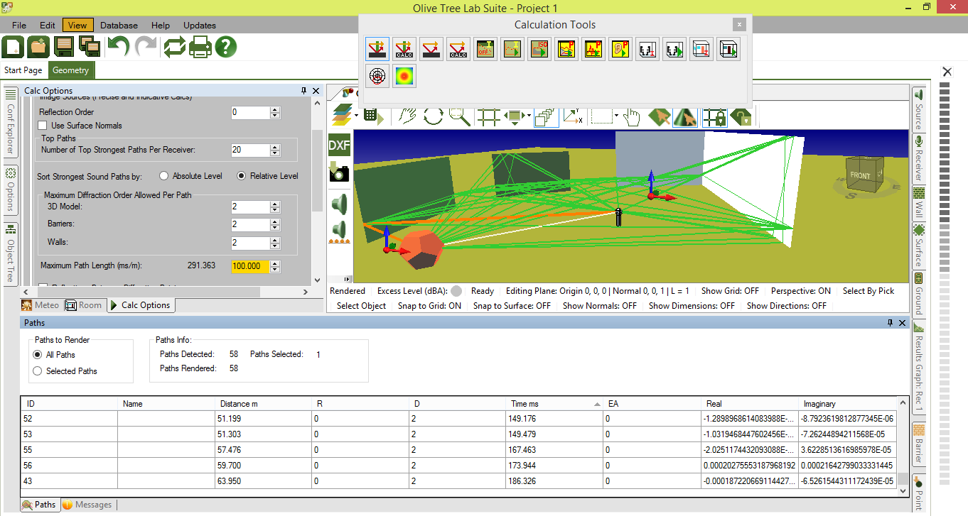
It can be a bit confusing to understand at first so it might be a good idea to set up a simple model with multiple walls and barriers and to play around with the settings. For example:
If the '3D model', 'Barriers' and 'Walls' are all set to 2 you will find 2 order of diffraction paths that diffract on walls only, 2 order of diffraction paths that diffract on barriers only but if a path diffracts from a wall and a barrier the maximum order of diffractions on both the walls and the barrier would be 1.
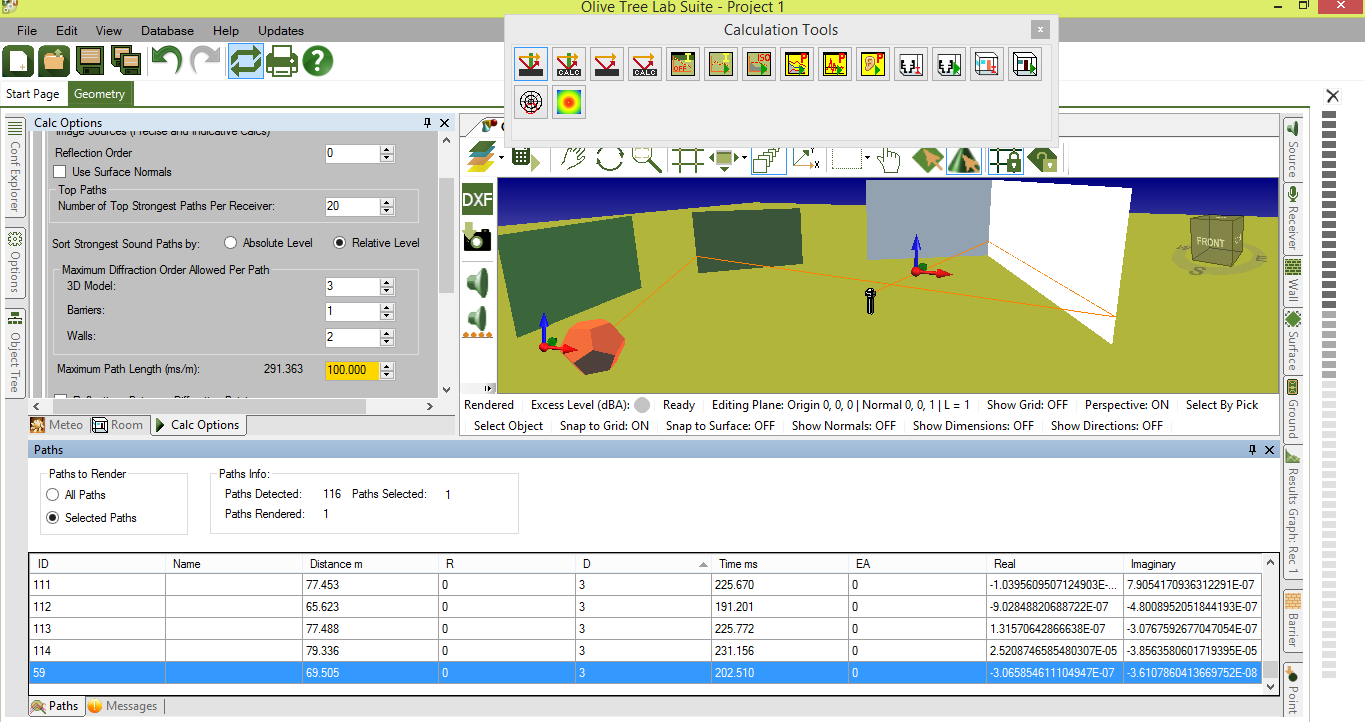
- By contrast if the '3D model' is set to 3, 'Barriers' to 1 and 'Walls' to 2 then you would be able to get a path with a maximum diffraction order of 3 that that diffracts on a barrier only once and wall twice. You would not be able to get a diffraction order of 3 that diffracts on a barrier twice and a wall once because of settings that limit those orders in the 'Barriers' and 'Walls' field. Also the maximum diffraction order of paths that diffract on walls would be two, and on barriers one.
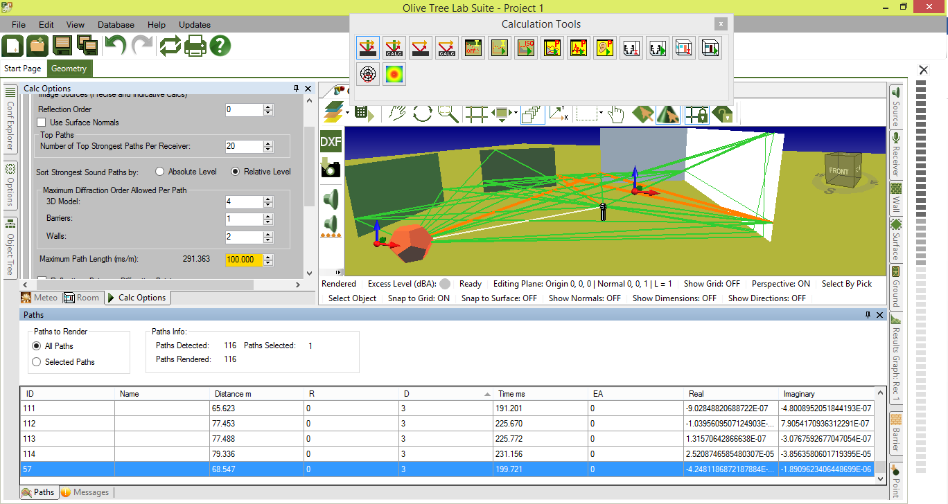
If you then changed the '3D model' setting to 4 and kept the other settings the same, you would not actually get a diffraction order of 4 because the maximum diffraction order on walls and barriers is limited to 2+1=3.
When making a calculation with a sound speed gradient I get a warning about multiple grounds. Should I ignore it?
- If the model only includes a positive gradient (with no wind) then it can be ignored. If there is a negative gradient anywhere in the atmosphere then see Refraction section in the Help Files.
I made a calculation with atmospheric refraction and I am getting extremely high sound levels (such as 200 dB).
- An issue with the extremely high sound levels can occur due to a receiver being in the shadow zone of sound sources. One limitation of the shadow zone is that it assumes a flat terrain. If multiple terrains are present in the OTL-Suite model the XY plane at z=0 is used as the ground for calculations. You can read more about it in the section of the help files in 'Calculations & Calculation options'>'Outdoor Sound Propagation Calculations'>'Refraction' in the 'Shadow Zone Calculations with a General Terrain' section at the end of the page.
- You will need to use the 'generate average ground' tool from the 'cad tools' window which will replace all your grounds with a single average ground. Please make sure that you clone your existing configuration and do this in a new configuration so that you do not lose your original grounds.
- Next some of the walls, sources or receivers may fall above or below the ground. Select them and readjust their heights so that they are roughly in their original relative heights above the ground. You can easily do this by selecting them and using the 'PgUp' and 'PgDn' shortcuts to shift them up and down in the z-direction.
- Alternatively, if you are looking to investigate worst case scenarios it is probably better to just reverse the wind direction in the 'meteo' side panel so that the dwelling area is not in the shadow zone. Downwards refracting paths tend to be much louder than the creeping wave of the shadow zone calculation.
What is the difference between the ‘Set’ and ‘Calculate’ options for the sound speed gradient section in the ‘Meteo’ side panel?
- Set, indicates whether the user will set the sound speed gradient.
- Calculate, indicates whether the user will define the necessary parameters to calculate the sound speed gradient in the ‘Sound Speed Gradient Parameters’. These could be used in cases where meteorological measurements are available such as Temp at height, Wind speed, etc...
I made a calculation with multiple sources together and I would like to see the contribution of each source individually. Is this possible?
- It is not possible to see the contribution of the individual noise sources in OTL-Suite, however the individual contribution can be exported to a third party software such as Excel from the Output Window, by right clicking a calculation and selecting ‘Export Transfer Function Before/After to CSV/Clipboard’. The exported data will be the complex pressure based transfer function that will need to be converted to decibels.
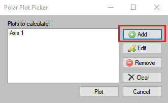
Can I run multiple Polar Plots with different frequencies?
- You can run multiple polar plot calculations with different frequencies by inserting different axis in the 'Polar Plot Picker' window using the 'Add' button multiple times:
Once you click 'Add' and the 'Polar Axis Picker' window pops up, you can then click the 'Use Last Axis' button in the 'Polar Axis Picker' to select the exact same axis each time you add a new axis:
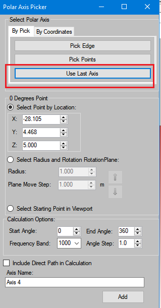
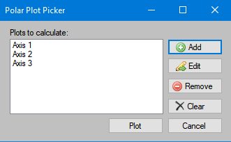
For each new axis you can just change the frequency band. You will get a list of the axis that will be calculated in the 'Polar Plot Picker' window:
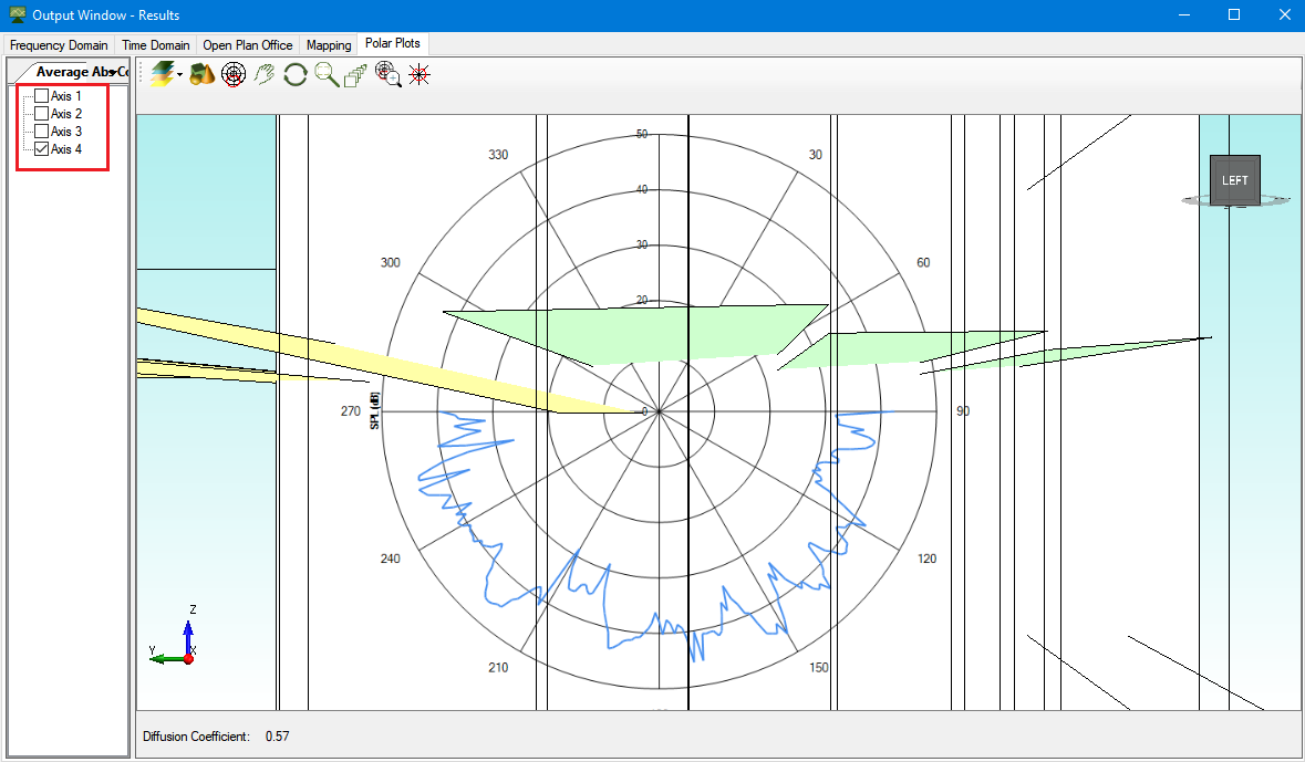
When you click the plot button all the axis in the list will be calculated at the same time. These will be presented in the Output Window as separate plots:
Is it possible to do batch simulations in OTL-Suite.
- It is not possible to do batch simulations in OTL-Suite.
Can I set different simulations so that they run simultaneously?
- The only way to run multiple simulations at the same time is to open multiple sessions of OTL-Suite and run each calculation at the same time. The calculations results will need to be imported from one project to the other in order to be compared.
I changed the material of a barrier and the calculation results are affected. But I thought that the attenuation factor due to edge diffractions does not depend on the surface material?
- The reason there is further noise reduction with a more absorptive barrier is due to the fact that every time you calculate one diffraction path the calculation includes four sub-paths (not shown anywhere in OTL-Suite) which are shown in Fig 2 in the paper by Allan Pierce and W. James Hadden (1981 - 'Sound diffraction around screens and wedges for arbitrary point source locations') whose methodology is applied in OTL-Suite.
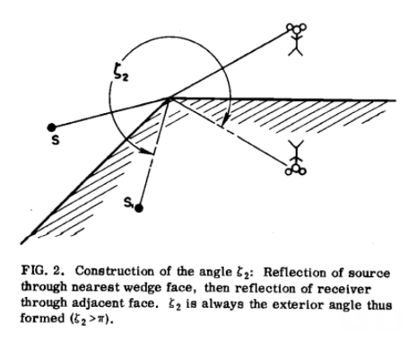
In essence and in combination of Fig. 2 there are the following paths, described by Eqs 2 in paper:
- source to rec
- image source to image receiver
- image source to receiver
- source to image receiver
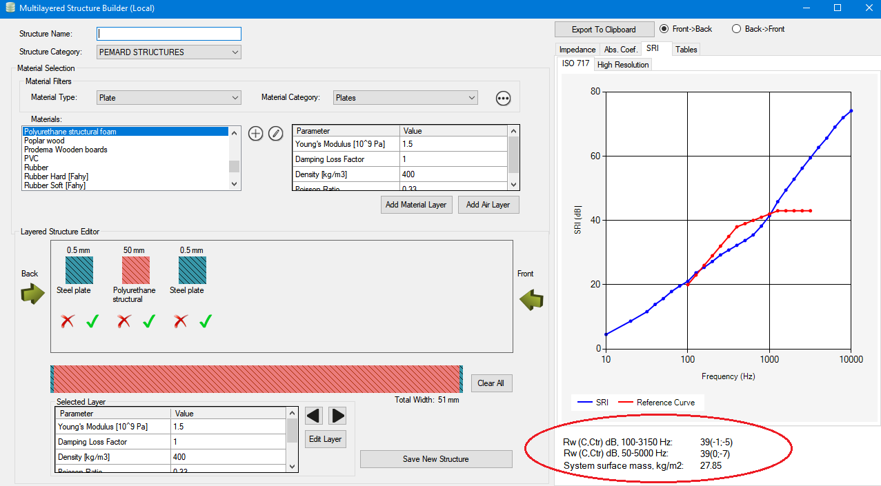
Are the SRI values of a material ever used in the calculations in OTL-Suite?
- SRI values, are part of the building acoustics module which is currently under development and not available. OTL-Suite does not handle sound transmission, but if you wish to see the Rw and SRI values of structures, then you can do so in the multilayered structure builder as shown below:
Are paths calculated parallel to each other or after each other?
- Yes, paths are calculated in parallel.
Would increasing the CPU of my computer increase the speed of calculation in OTL-Suite?
- Yes, upgrading the CPU would be beneficial.
I created a Plate-Air-Plate system in the Multilayered Structure builder and the resulting SRI is strange.
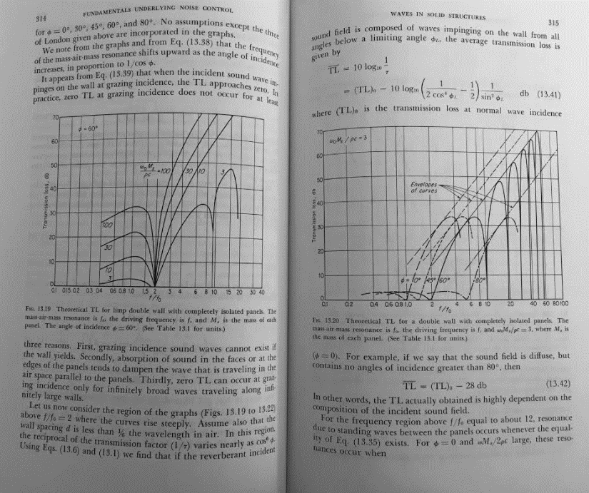
- It is important to keep in mind that the calculated SRI shown in the graph in the Multilayered Structure Builder is the statistical SRI which averages the SRI of the structure at various angles of incidence. One important consequence is that for Plate-Air-Plate structures the first resonance dip of the SRI shifts with different angles of incidence and when you average them the resonance dip gets 'smeared' along the frequency domain. You can see this in the figure below taken from the textbook 'Noise Reduction' by L. Beranek:
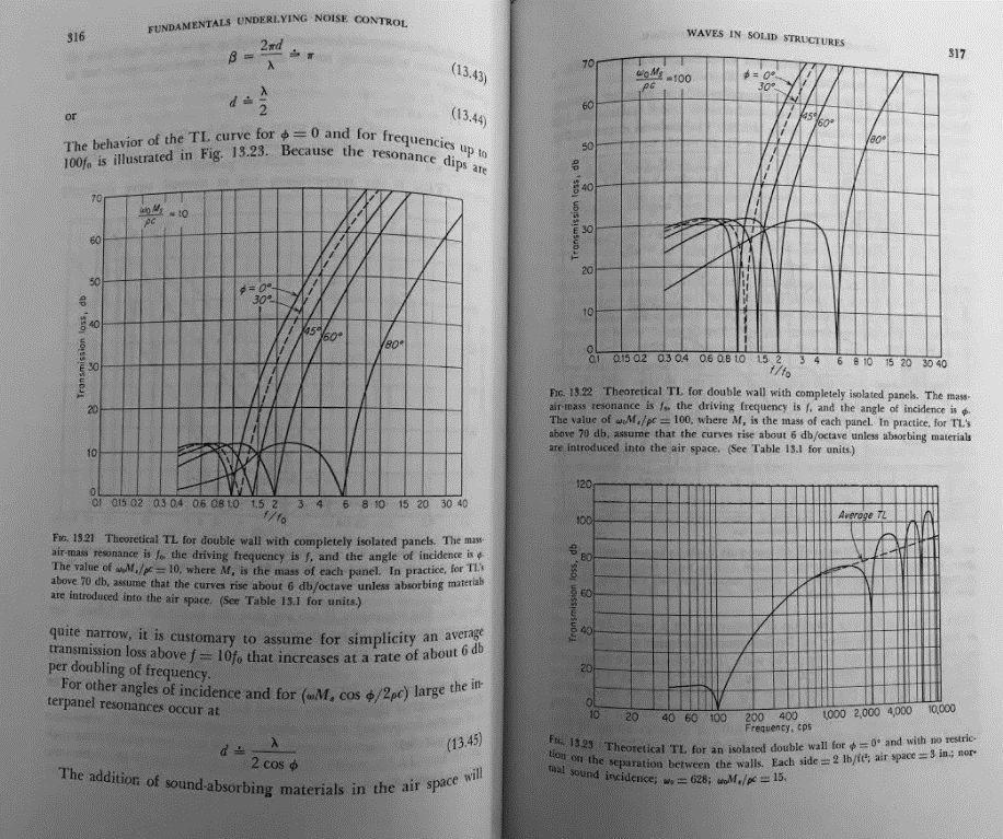
- In Figure 13.21 above different curves correspond to different angles of incidence and if you average these curves you will get a wide resonance dip across that range. By contrast when you look at a single angle of incidence and change other parameters (such as mass) the resonance dip remains fixed (Figure 13.19 below):
What is the best way to model laminated glazing panes in the Multilayer Structure Builder?
- The best way is to model it by inserting each individual laminated layer for each pane. You can compare the differences in the two screenshots below (the top screenshot is a laminate structure with each laminate layer inserted individually, and the bottom screenshot is a structure with the same dimensions/materials but with each pane modelled as a monolithic glass pane):
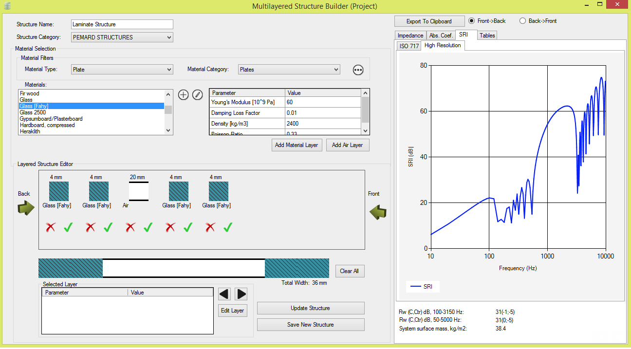
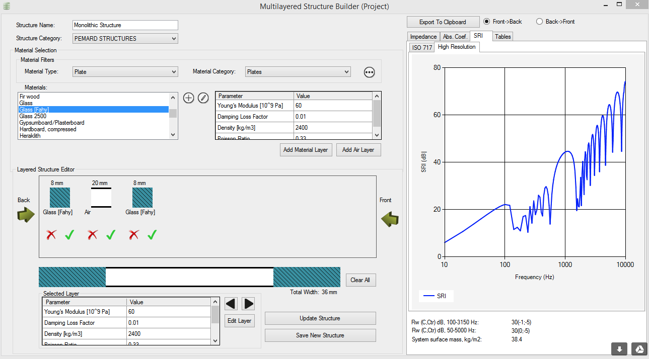
The difference affects the critical frequency (the second resonance dip).
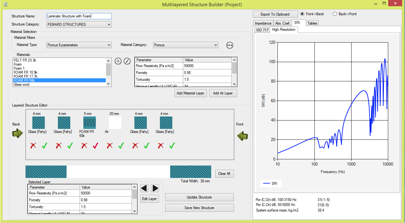
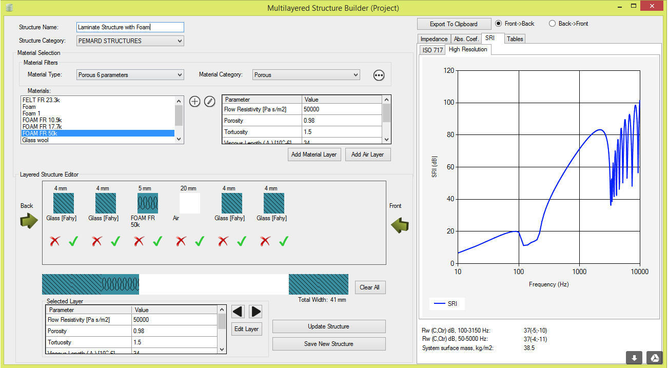
How are sound bridges calculated in the Multilayered Structure Builder
- For the time being, only Sharp’s simplified method of taking into account sound bridges is implemented in OTL-Suite based on Atalla's [See References section in Help Files] paper. One can smooth the response by adding a porous layer between a plate and cavity to account for some damping losses in the structure, as shown in the screenshots below (top screenshot with foam layer disabled, bottom image with foam layer enabled). In the future when we finish developing the Building Acoustics module of OTL-Suite we will incorporate the latest bridging model by Atalla.
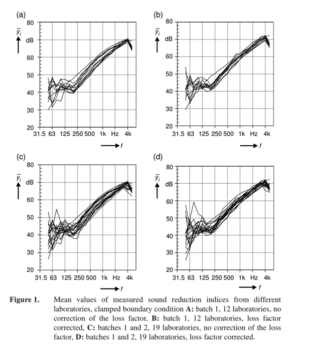
When comparing SRI laboratory measurements of a structure to the calculated results in the Multilayered Structure Builder I get accurate results in the high frequencies but large deviations in the low frequencies.
- Regarding low frequencies in SRI a variation of 10-15 dB is not actually unusual between laboratory measurements. The figure below is taken from the 2005 paper ‘Using Round Robin Test Results for the Accreditation of Laboratories in the Field of Building Acoustics in Germany’ (attached in this email) and compares the SRI of a partition in different laboratories:
The figure below is similar but for partitions with elastic boundary conditions:
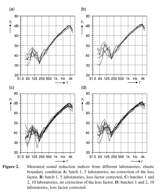
Therefore, you shouldn’t be too concerned with trying to match low frequencies with laboratory measurements as the uncertainties are so high.
What are the limitations of the models used in the multilayered structure builder (MLSB) in OTL-Suite?
Possible limitations of the models used in the MLSB of OTL are as follows: panel resonances are not taken into account, panels are infinite in dimension so no edge effects are taken into account and the Niche effect is not modelled.
For the SRI calculations is it possible to calculate specific angles of incidence? Does OTL-Suite take incidence angles into account?
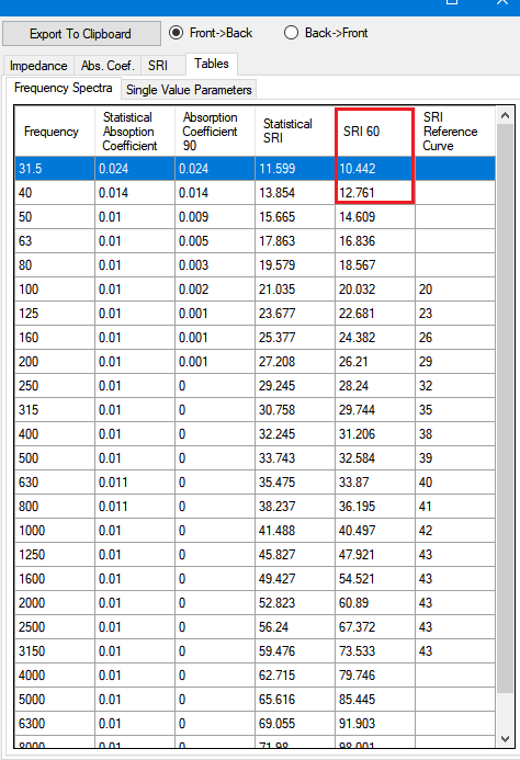
- OTL-Suite only gives the 60 degree angle of incidence for SRI calculations (along with the averaged), which you can find in the 5th column of the 'Tables>Frequency Spectra' tab in the Multilayered Structure Builder.
Of Course, for the noise calculations specific angles are always considered for calculating the reflection and diffraction factors (transmission is not yet modelled in OTL-Suite)
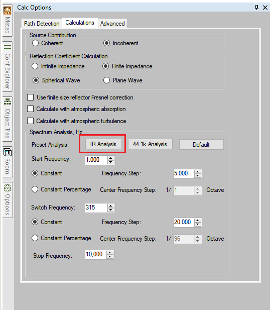
I was trying to run a room acoustics calculation, and I have received a warning saying that ‘This calculation is not going to calculate an IR. In order to calculate an impulse response, you need to change the spectrum analysis.’ Do they mean the spectrum of the sources?
- The warning is only relevant if you want to calculate the impulse response, else you can ignore it. If you want to calculate the IR then the spectrum refers to the frequency spectrum in the ‘Calc Options’ side panel, not the source spectrum. Just click the 'IR Analysis' button in the Calc Options>Calculations side panel and OTL-Suite will calculate an impulse response:
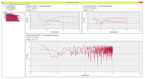
In the High Resolution graph in the Output Window, the Level Before/Level After/Level Free Field curves are always in 1/3 Octave resolution, whereas the IL/EA Before/EA After curves have the resolution specified in the Calc Options side panel.
- Level Before/After/Free Field, are always in 1/3rd Oct bands since they include source characteristics which are usually given in 1/3 Oct bands. IL, EA Before/After are shown in any resolution from 0.001 to 100KHz because these parameters are independent of source characteristics and are only dependent on 3D model properties which we handle at any resolution.
- Please remember when we carry out experiments we try to eliminate from the results the effect of the source since the phenomena studied are independent of the type of source one uses.
I sent a model which included a refractive atmosphere to the origin and the results are different.
- If your model contains multiple grounds and has a receiver in the shadow zone of a source then theoretically the results changing the origin will change the results because when multiple grounds are present the XY plane is taken as the reference ground (since the shadow zone model can only take one ground as reference OTL-Suite cannot know which ground take as a reference. Therefore it takes the XY plane as the reference by default which is why sometimes there may be problems with the results).
- This is why we added the new 'Generate Average Ground' tool as it is the only way to get correct results. The tool replaces multiple grounds with one averaged ground, averaging their height and inclination using the least squares method. That way, when a shadow zone calculation is performed it takes that averaged ground as a reference which means the results will always be correct and you won't get the unnaturally high levels for the high frequencies.
- Because the original grounds get lost when you do this, it is a good idea to do this in a new configuration. You can also just do this only with the problematic receivers that are in the shadow zone and do the rest of the calculations with the multiple grounds.
I ran a Reverberation Time calculation and the results are strange.
- Check the normals of all your active surfaces. Use the 'Auto Correct Normals' tool from the 'CAD Tools Window' to fix most of them and then inspect each active surface to ensure that the arrow is pointing towards the interior of the room. Surfaces whose both sides are exposed to the interior of the room should be double sided. If an active surface has a normal that is not pointing towards the interior of the room, select that surface, right-click, and select the 'Flip Normals of Selected Surfaces' option from the right - click menu. You can find more information on surface normals in the 'Using CAD Tools' section of the Help Files.
- Also minimise as many of the surfaces as you can to speed up calculations. If the model was imported from a .dxf/dwg file select the 'Optimised' option to minimise the surfaces.
Is there any way to see the paths used for the ISO Calculation? Does the ISO calculation only consider one reflection order for each path?
- ISO calculations only consider one reflection for each path, however, the Path Explorer detection is only possible for the Precise Calculations.
I ran an ISO calculation in OTL-Suite over a barrier and the calculations don’t match my manual calculations.
- Make sure you include paths from the sides of the barrier in your manual calculation.
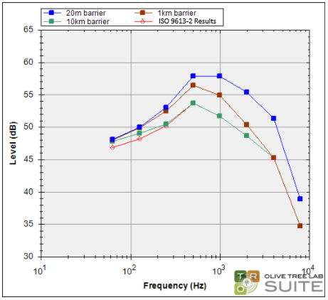
- Alternatively if you keep making the barrier wider the OTL results will begin to approach the results of manual ISO 9613-2 calculation with only the diffraction path from the top of the barrier included:
- There may also be some minor discrepancies due to the way atmospheric absorption is calculated. OTL uses the procedure specified in ISO 9613-1.
I have some noise sources which do not have a direct line of sight with the receiver. I set the diffraction order high enough so that diffraction paths should be found but I couldn’t find any.
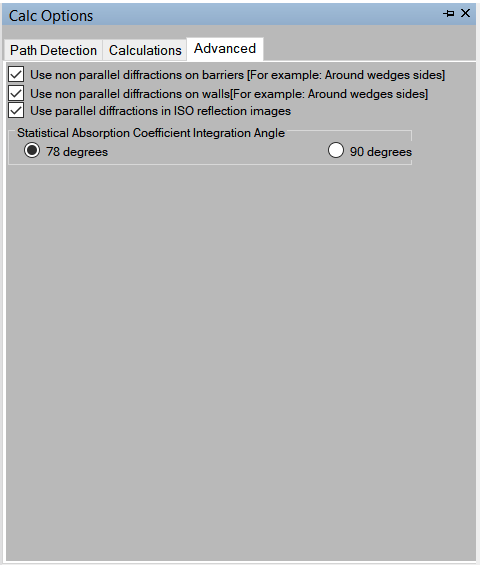
- You may also need to enable the Non-Parallel diffractions on barriers and walls found in the ‘Advanced’ tab of the ‘Calc Options’ side panel.
Why are the T60, Sabine and Eyring curves so different? Does it depend on the room shape?
- T60 (or T30, T20 and EDT) is the reverberation time calculated using OTL-Suite's Hybrid Ray Tracing Method (which might result in slightly different values between two calculations of the same setup which is inherent in the method). Sabine and Eyring are statistical models that do not take into account sources and receivers in the room only the room's shape and absorption properties.
- The main difference between the statistical models (Sabine and Eyring) and the Hybrid Ray Tracing Method is that the statistical models assume a diffuse field whereas the Hybrid Ray Tracing Method does not. If the room field is not diffuse then there will be a difference between the statistical models and the Hybrid Ray Tracing method, since the Hybrid Ray Tracing Method takes into consideration the positions of the source and receiver.